Fats, oil and grease – known as FOG in the industry – do not belong in wastewater. If large quantities of FOG enter the sewers, they can cause considerable damage and lead to corrosion, odours and blockages. In recent years, the sewers of London have made the headlines, with the discovery of vast fatbergs. To prevent this, it is mandatory in virtually all business in which greasy wastewater occurs, to use grease separators that are designed and sized to European standard EN 1825, for example, in restaurants, commercial kitchens or butcher’s shops. Grease separators largely remove the grease and oil in wastewater before it is discharged into the sewers. Yet which separator is suitable for which area of use and which system is designed for which installation situation? The separators are frequently located in cramped basement, which make their installation difficult. At the same time, guests should not be exposed to possible odours released during the necessary disposal process.
Cleaning wastewater by gravity
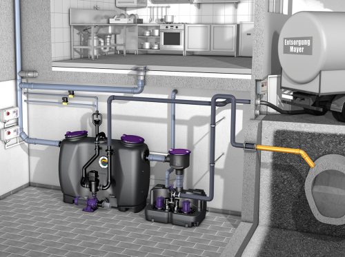
All grease separators have one thing in common: they clean the greasy wastewater with the help of gravity. The substances in wastewater that are heavier than water sink (Figure 1) to the bottom where they collect in the sludge trap. Above is the grease separator tank. This is where the oils and greases separate from the wastewater, as they are less dense than water and float to the surface. A continuously growing grease layer forms. The largely cleaned wastewater is discharged through an outlet.
The installation options
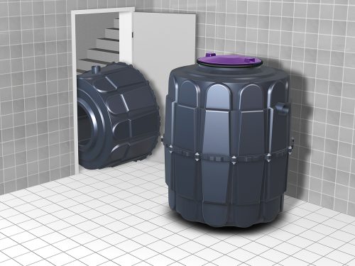
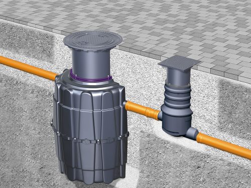
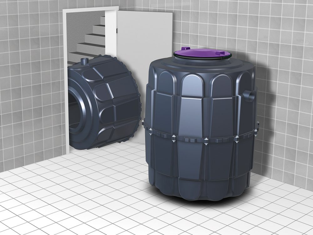
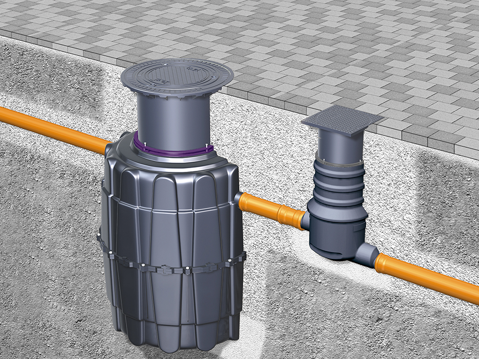
Grease separators can either be installed as a free-standing installation inside the building (Figure 2) or in the ground externally (Figure 3). Sufficient space is required for installation, operation, maintenance and inspection of the separator and the room in which the separator is installed must not be used to store food. Ensure adequate ventilation. In addition, a water connection is necessary for filling and cleaning the separator, and an electrical installation is also necessary.
If a grease separator is to be installed in the ground, it should be located outside the trafficked area. A separator installed in the ground must, of course, be accessible at all times for maintenance, checking and disposal.
In general, separators should be installed near the kitchen. The supply pipes must have a gradient of at least 2 percent to prevent grease accumulations. If this is not possible for structural or operational reasons, and/or if longer pipes are necessary, suitable measures must be taken to prevent grease accumulation and deposits. To prevent odour nuisance, the separator should not be located near common rooms and in particular it must be sited away from windows and ventilation openings. Disposal vehicles must be able to reach the separators easily to make disposal fast and simple.
The suitable lifting station for grease separators
According to EN 752-1, a downstream twin lifting station (Figure 5) is required if the grease separator is installed below the backwater level, or if gravity flows to the wastewater network are not feasible.
Odourless disposal? – how to find the right disposal option
Different disposal versions are available, depending on where the separator is located, how frequently it must be emptied and what disposal options are available:
|
Version |
G1 |
D2 |
D+S3 |
D+SP4 |
M+S5 |
PV+S6 |
|
Odour-free disposal The direct disposal connection enables the contents of the separator to be extracted by the disposal vehicle without opening the covers of the separator. |
|
X |
X |
X |
X |
X |
|
Odourless disposal The integrated Shredder-Mix system homogenises, flushes and cleans the inside of the separator. |
|
|
X |
X |
X |
X |
|
Disposal pump If the disposal vehicle is too far away from the grease separator for the vehicle’s vacuum disposal system to operate, the separator is equipped with its own disposal system. |
|
|
|
|
X |
X
|
|
Fully automatic and remote control (option) All preprogrammed disposal steps take place fully automatically. |
|
|
|
|
|
X |
1) The designation “G” stands for basic version. The odour-tight domed covers of the grease separator have to be opened for emptying and cleaning. Extraction and rinsing of the grease separator takes place manually from the disposal vehicle.
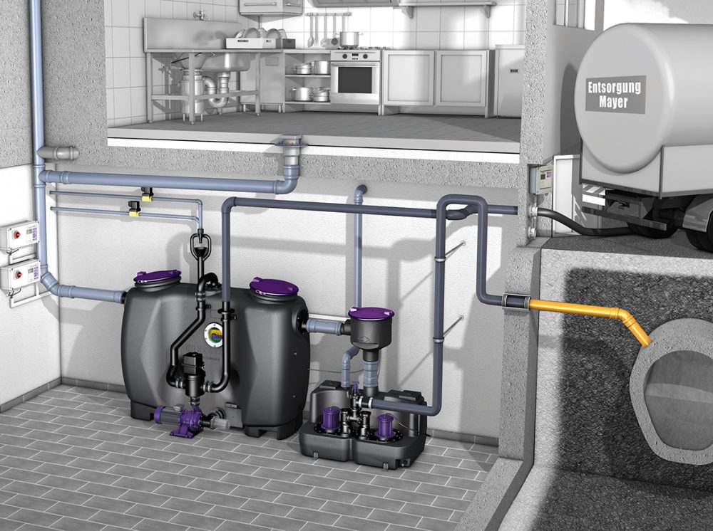
2) The designation “D“ stands for grease separator with direct disposal. The contents of the grease separator are extracted from the closed tank, through pipes permanently installed on site, by the disposal vehicle’s pump. This pump is connected to the pipes outside the building.
3) Grease separators with direct disposal and “Shredder-Mix system” (D+S) are emptied by extraction through pipes permanently installed on site. These are connected to the disposal vehicle’s pump outside the building. This means there are no odour emissions during emptying. The “Shredder-Mix system” is used to macerate and circulate (reduce the size of) the entire contents of the grease separator tank. Maceration, mixing and cleaning are all carried out simultaneously.
4) In “D+SP” systems, the Shredder-Mix pump and two solenoid valves are operated automatically by a control unit to fill/clean the tank.
5) The designation “M+S” stands for grease separator with manual disposal and flushing equipment and the “Shredder-Mix system”.
6) The designation “PV+S” stands for KESSEL grease separator with program-controlled, fully-automatic disposal and flushing equipment as well as the “Shredder-Mix system”.
Emptying intervals – standardised or needs-based
The emptying of the separators and disposal of the contents must conform to EN 1825. The disposal intervals must be defined so that the storage capacities of the sludge trap (half the sludge trap volume) and of the separator (grease collection tank) are not exceeded. According to the relevant standard, the sludge trap and separator must be completely emptied, cleaned and refilled with fresh water at least once a month, or preferably every two weeks.
Yet what happens if the grease storage element is still not full after a month? More and more local authorities offer businesses that produce relatively small quantities of grease the possibility of extending the disposal interval. Automatic layer thickness measuring devices for grease separators such as SonicControl (Figure 5) enable exact monitoring and automatic measurement, display and control of the layer thickness as well as the temperature. The owner-operator can read off the calculated thickness of the grease layer at the control unit. The control unit indicates that disposal is necessary before the maximum is reached. Remote monitoring is also possible. This enables safe, reliable and needs-based disposal.
Online design tools
The “SmartSelect” online tool helps you to find the right separator. Visit https://www.kessel.com/service/smartselect-design-assistant.
